ぜひ弊社まで サーバーシャーシ エンジニアおよび営業チーム




チャンネル登録者数24,000人
お客様の用途、シャーシの種類、ラックの高さ、マザーボード、GPU、ドライブベイ、電源、冷却システム、I/O、および注文数量をお知らせください。当社のエンジニアおよび営業チームが、お客様のプロジェクトに適した標準モデルまたはOEM/ODM構成をご提案いたします。.
チャンネル登録者数24,000人
お客様の用途、シャーシの種類、ラックの高さ、マザーボード、GPU、ドライブベイ、電源、冷却システム、I/O、および注文数量をお知らせください。当社のエンジニアおよび営業チームが、お客様のプロジェクトに適した標準モデルまたはOEM/ODM構成をご提案いたします。.

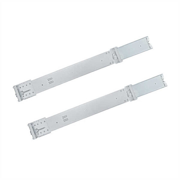
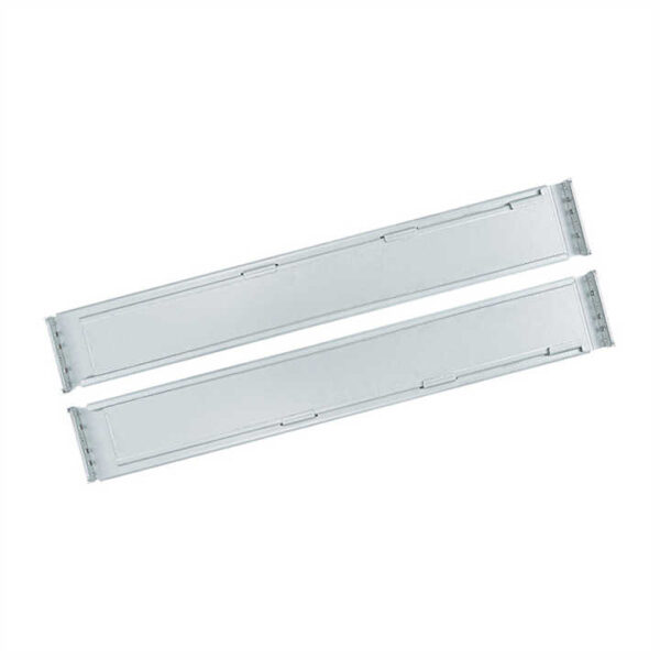
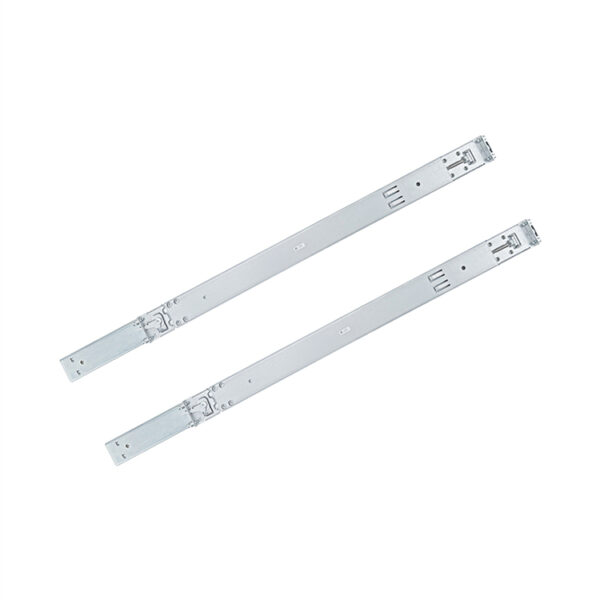
A chassis guide rail is a supporting and sliding accessory that aligns compatible rack-mounted equipment during insertion, removal, or service access. Engineers, system integrators, equipment manufacturers, security installers, and procurement teams may need it when an electronic enclosure requires controlled support inside an equipment rack.
This component provides a defined path along the sides of compatible rack-mounted electronics. It supports an enclosure while the unit is positioned during installation, removal, inspection, or maintenance, reducing the need to hold the full weight in alignment by hand.
Unlike a fixed shelf, a paired side-support system is normally matched to a particular enclosure and rack arrangement. The exact travel method, fixing pattern, and included hardware vary by configuration, so model-specific drawings and equipment documentation should control the final decision.
Compare key chassis guide rail parameters in one clear table, including rail length, adjustable range, rack depth, mounting configuration, extension type, load requirements, and compatible chassis models. Use the comparison to shortlist a suitable option, then confirm the exact chassis and rack fit before ordering.
| 商品画像 | モデル製品リンク | 対応シャーシ | 外形寸法(L×W×Hmm) | 最大荷重 | キャビネットの奥行き |
|---|---|---|---|---|---|
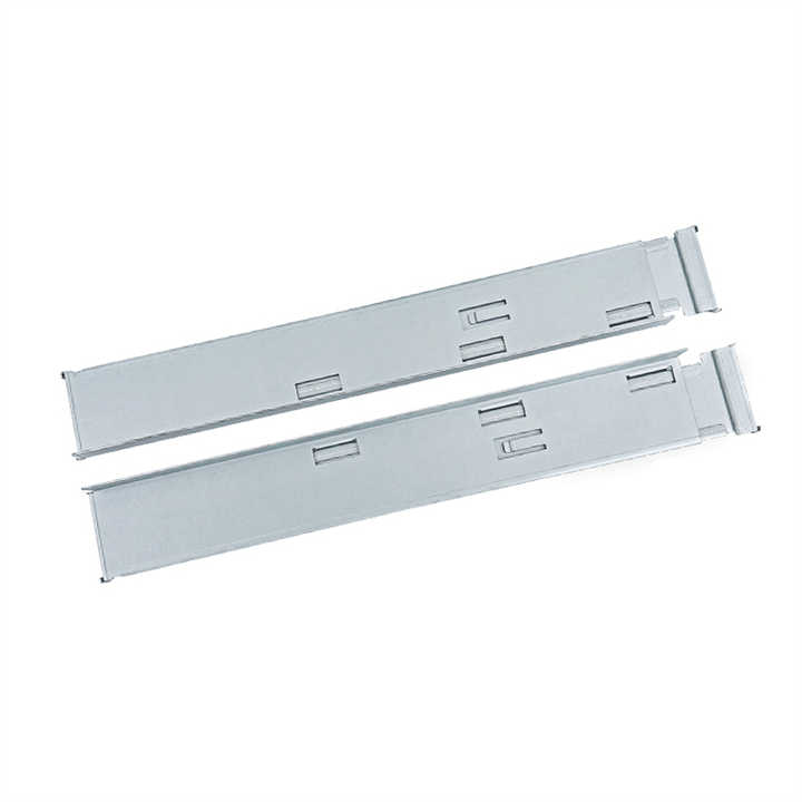
| 1U 2U 3U 4U ラックマウントサーバーシャーシ L型ガイドレール | 1U-4Uサーバーシャーシ | 620×93×47 | 100キロ | 800-1200 mm |
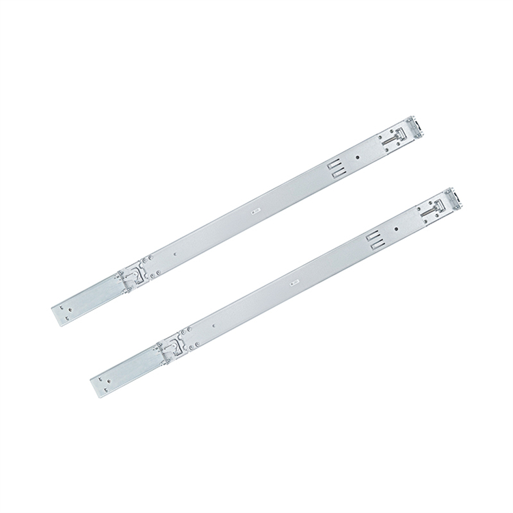
| 1U 2U サーバーシャーシガイドレール 600-0040 | 1U & 2U server chassis | 743×-×43.5 | 38キロ | 800-1000mm |
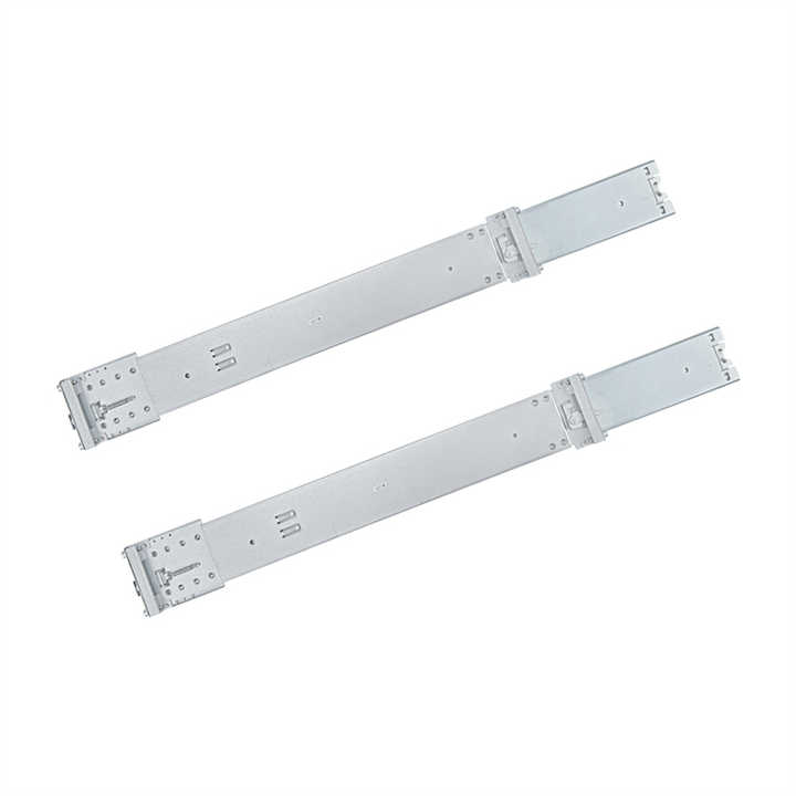
| 4Uサーバーシャーシガイドレール800-1200 | 4Uサーバーシャーシ | 785×-×76.2 | 70キロ | 800-1200 mm |
Correctly matched supports can make equipment handling more convenient by keeping the enclosure aligned with the rack opening. They can also enable efficient maintenance access, help protect adjacent equipment from unnecessary contact, and reduce unwanted side-to-side movement while a unit is being positioned.
The practical value is controlled support rather than universal compatibility or unlimited load. Durability depends on the confirmed material, construction, operating environment, and whether the equipment weight remains within the stated Load Capacity.
Begin with the dimensional drawing and mounting configuration. Important fields include Rail Length, usable rack depth, enclosure height such as 3U or 4U where applicable, front and rear fixing locations, hole pattern, available travel, extension type, and clearance around cables or handles.
Also confirm [Material], surface finish, Load Capacity, left-and-right orientation, included fasteners, and whether the design is fixed, partial-extension, or another verified format. A product drawing should identify all critical measurements instead of relying on a broad description.
Likely applications include rack-mounted electronics, NVR recording equipment, server enclosures, industrial control equipment, test systems, plug-in units, and compatible subrack assemblies. A particular item may suit only Compatible Models , even when two units share the same rack height or appear visually similar.
This equipment-rack component is not an automotive frame member or vehicle structural part. It is intended for electronic enclosures, and fit must be checked for the exact equipment and rack combination. Manufacturer compatibility resources commonly compare rack flange type, depth, support format, and adjustment range.
Typical setup begins by identifying the left and right components, locating the correct rack-unit position, and aligning the fixing points at equal heights. The installer then secures both sides according to the equipment manufacturer’s instructions and checks that the supports are parallel before inserting the enclosure.
Never force a unit that binds, tilts, or sits unevenly. Verify dimensions, fastener engagement, cable clearance, and movement through the required access range before the equipment is placed into operation.
A chassis guide rail supports and aligns compatible rack-mounted equipment during insertion, removal, and maintenance access.
No. Compatibility depends on the equipment model, chassis dimensions, rack depth, mounting format, and rail adjustment range. Manufacturers commonly provide model-specific compatibility information.
Yes, provided the rail dimensions, fixing points, and load requirements match the specific NVR, server chassis, or industrial enclosure.
Install the left and right rails at the same rack-unit height, keep them parallel, and follow the equipment manufacturer’s instructions before sliding in the chassis.
Provide the equipment model, chassis size, rack depth, mounting points, expected load, required rail length, order quantity, and service-access requirements.
Share your equipment model, chassis dimensions, rack depth, mounting points, expected load, and service-access requirements. We’ll review the details and recommend a suitable rail configuration for your application.