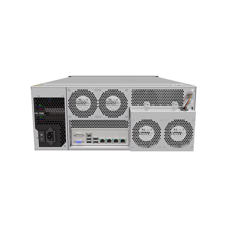
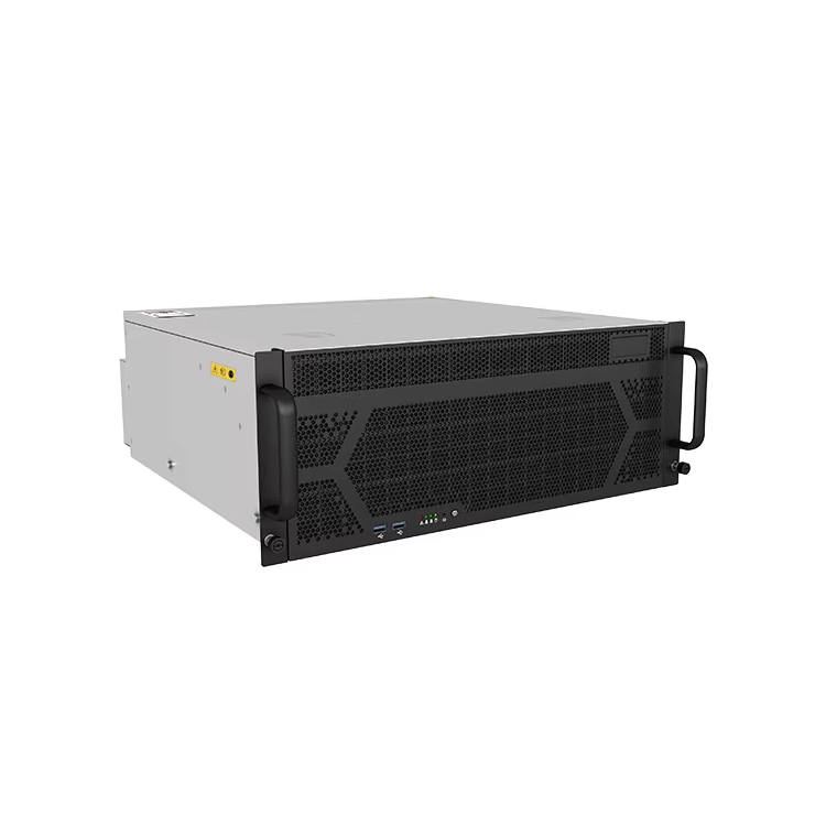
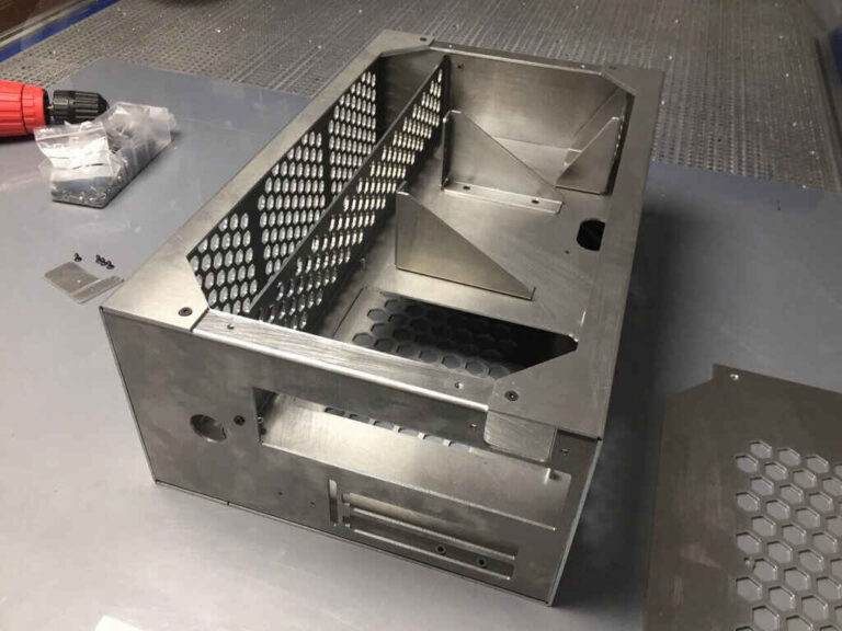
A مراجعة DFM, ، أو «مراجعة التصميم من منظور قابلية التصنيع»، هي العملية الهندسية التي تُستخدم لتقييم مدى توافق تصميم هيكل خادم مخصص مع متطلبات التصنيع الفعلية قبل الإذن ببدء إنتاج النموذج الأولي أو الإنتاج بكميات كبيرة.
وهو يطرح سؤالاً يبدو بسيطاً للوهلة الأولى:
هل يمكن تصنيع هذا الهيكل بشكل متكرر، وفحصه عمليًّا، وتجميعه بكفاءة، وبيعه بالسعر المستهدف دون تغيير وظيفته المطلوبة؟
تصميم التصنيع (DFM) يغير كل شيء.
قد يكون هيكل الخادم مكتمل الأبعاد في برامج STEP أو SolidWorks أو Inventor أو أي بيئة CAD أخرى، ولكن بمجرد دخول عوامل مثل القطع بالليزر، وأدوات ثني الصفائح، ومكونات PEM، والتشوه الناتج عن اللحام، والطلاء بالمسحوق، ومسار الكابلات، وتراكم التفاوتات، واستراتيجية الفحص، وتجميع المشغل في المعادلة، فإن هذا النموذج الذي يبدو مكتملًا قد يتحول إلى مشكلة تصنيعية بعيدة كل البعد عن الاكتمال.
فلماذا نكتشف ذلك بعد أن يكون المعدن قد قُطِع بالفعل؟
أنا أتخذ موقفًا صارمًا إلى حد ما في هذا الشأن. فإذا تلقى أحد المصنعين طلبًا لتصنيع هيكل مخصص معقد، وقدم عرض أسعار له على الفور، ثم عاد دون أن يطرح أي أسئلة هندسية، أو يبدي أي تعليقات على الرسومات، أو يثير أي مخاوف بشأن التفاوتات المسموح بها، أو يقترح أي تغييرات في العملية، أو يناقش الكمية السنوية، فإنني لا أعتبر هذا الصمت دليلًا تلقائيًّا على الكفاءة.
في بعض الأحيان يكون الرسم رائعًا حقًّا.
في كثير من الأحيان، يكون المورد ببساطة لم يعترض على ذلك بعد.
هذا التمييز مهم.
ما الذي يُفترض حقًّا أن تحققه مراجعة DFM
يُعتبر التصميم من أجل التصنيع (DFM) في بعض الأحيان بمثابة الفحص النهائي لتصميمات CAD.
هذا كلام سطحي للغاية.
خطير تصميم ملائم للتصنيع (DFM) لهياكل الخوادم المخصصة تربط عملية المراجعة بين تصميم المنتج ونظام التصنيع الفعلي الذي سيتولى إنتاجه. وقد يراعي مهندس التصميم عوامل مثل موقع اللوحة الأم، والمسافة الفاصلة عن وحدة معالجة الرسومات (GPU)، وموضع المروحة، وسعة محرك الأقراص، وعمق الحامل، وإمكانية الوصول لأغراض الصيانة. أما هندسة التصنيع، فيجب عليها ترجمة تلك المتطلبات إلى عمليات القطع، والتثقيب، والتشكيل، واللحام، والتثبيت، والتشطيب، والتجميع، والفحص، والتعبئة، والإنتاج المتكرر.
يجب أن يتفق كلا الرأيين.
يقدم المعهد الوطني للمعايير والتقنية (NIST) الحجة الاقتصادية بوضوح. وتشير أبحاثه حول التصميم المراعي للتكلفة وتقدير تكاليف التصنيع تشير الدراسة إلى أن الأبحاث قد أثبتت مرارًا وتكرارًا أن تكلفة التغييرات في التصميم تزداد في المراحل المتأخرة من تطوير المنتج، ولهذا السبب تعمل منهجيات «التصميم من أجل X» على إدراج اعتبارات قابلية التصنيع والتكلفة والقيود الأخرى في القرارات الهندسية في المراحل المبكرة.
وهذا المبدأ ينطبق بشكل مؤلم على هياكل الخوادم.
يُعد نقل فتحة الموصل في برنامج CAD عملية غير مكلفة.
أما نقله بعد وجود 500 لوح أمامي مطلي، فهذا ليس كذلك.
تتناول وكالة ناسا (NASA) هذه المسألة نفسها من منظور الممارسات الهندسية. وتوصي إرشاداتها المتعلقة بقابلية التصنيع باعتماد تفاوتات واقعية، والاهتمام بتراكم التفاوتات، وتوفير الفحص الكافي وإمكانية الوصول إلى الأدوات، واعتماد أنصاف أقطار داخلية أكبر وعملية، ومواد متوفرة بسهولة، وتصاميم تتيح التفكيك. وقد وُضعت هذه التوصيات من أجل معدات الفضاء الجوي الأكثر تطلبًا بكثير، لكن المنطق الكامن وراءها ينطبق بشكل لافت للنظر على العلب المخصصة.
وهناك مشكلة أوسع نطاقاً تتعلق بالجودة تكمن وراء كل هذا. تشير الجمعية الأمريكية للجودة إلى أن 31% من المشاركين في الاستطلاع في دراسة ’تكلفة الجودة لعام 2025»، أفاد المشاركون بأنهم يدركون تمامًا كيفية تأثير تكاليف الجودة على الأداء المالي لمؤسساتهم. وتُعدّ المخلفات، وإعادة التصنيع، وإعادة الفحص، وأعمال الضمان، والمرتجعات، فئات معترف بها لتكاليف الجودة. إرشادات جمعية جودة أمريكا (ASQ) بشأن تكلفة الجودة
ولهذا السبب لا أحب عبارة “DFM المجاني”.”
هذه المراجعة ليست مجانية.
دائمًا ما يدفع أحدهم ثمن ضعف قابلية التصنيع. والسؤال الوحيد هو: هل ستدفع ثمن ذلك بوقت العمل الهندسي قبل الإنتاج، أم بالخردة، وإعادة العمل، والتأخيرات، وتغييرات الأدوات، وعمليات الفحص، وشكاوى العملاء بعد الإنتاج؟.
مراجعة DFM مقابل مراجعة التصميم مقابل التحقق من صحة النموذج الأولي
عادةً ما يخلط المشترون هذه المكونات معًا.
إنهما ليسا متماثلين.
مرحلة المراجعة
السؤال الرئيسي
المدخلات النموذجية
الناتج النموذجي
مراجعة المتطلبات
هل نقوم بتصميم الهيكل الصحيح؟
قائمة الأجهزة، وحدود سعة الحامل، المتطلبات الحرارية، الكمية، التكلفة المستهدفة
المتطلبات الهندسية
مراجعة تصميم هيكل الخادم
هل تعمل البنية الميكانيكية بشكل صحيح؟
التصميم ثلاثي الأبعاد، الواجهات، رسومات المكونات
التصميم الميكانيكي المعدل
مراجعة DFM
هل يمكن لعمليات المصنع المختارة تصنيعه بشكل متكرر؟
CAD، الرسومات ثنائية الأبعاد، المواد، التفاوتات المسموح بها، التشطيب، الحجم
تعليقات DFM والتغييرات التصنيعية المعتمدة
مراجعة النموذج الأولي
هل سارت عملية التصنيع الفعلي كما كان متوقعًا؟
عينة مخصصة للإنتاج، أجهزة حقيقية
تصحيحات تتعلق بالمقاس/الوظيفة
مراجعة الإصدار التجريبي
هل يمكن إنتاج أكثر من وحدة واحدة بشكل منتظم؟
دفعة إنتاج صغيرة
التصحيحات المتعلقة بالعمليات والجودة
إصدار الإنتاج
هل التكوين الخاضع للرقابة جاهز للإنتاج بكميات كبيرة؟
الرسومات النهائية بنظام CAD، وقائمة المواد (BOM)، والرسومات، وخطة الفحص
حزمة التصنيع التي تم إصدارها
الدليل الحالي بشأن الانتقال من التصميم باستخدام برنامج CAD إلى نموذج أولي للإنتاج ويشير إلى نقطة مهمة: يجب أن تتم عملية التصميم من أجل التصنيع (DFM) قبل إنشاء أول نموذج أولي مخصص للإنتاج، لأن النموذج الأولي يجب أن يختبر الافتراضات المتبقية بدلاً من إعادة اكتشاف المشاكل الواضحة المتعلقة بالانحناء، أو التفاوتات المسموح بها، أو التثبيت، أو سهولة الوصول.
هذا التسلسل مهم.
المتطلبات → التصميم باستخدام الحاسب الآلي (CAD) → التصميم الملائم للتصنيع (DFM) → النموذج الأولي → التحقق من الصحة → المراجعة → المرحلة التجريبية → الإنتاج.
ملاحظة:
CAD → الإنتاج → Panic → DFM.
الخطوة 1: يتحقق المصنع من اكتمال المدخلات
غالبًا ما لا تكون المشكلة الأولى في تصميم التصنيع (DFM) متعلقة بالهندسة.
هناك معلومات ناقصة.
قبل أن أثق في أي استنتاج يتعلق بقابلية التصنيع، أود أن تحدد حزمة المشروع على الأقل ما يلي:
ارتفاع حامل الهيكل والعمق الأقصى المسموح به؛;
طراز اللوحة الأم وإحداثيات فتحات التثبيت؛;
غلاف مبدد حرارة وحدة المعالجة المركزية؛;
طول وحدة معالجة الرسومات (GPU) وارتفاعها وسماكتها ووزنها واتجاه موصل الطاقة؛;
مواضع بطاقات PCIe؛;
عدد محركات الأقراص وبنية حامل الأقراص؛;
هندسة اللوحة الخلفية؛;
تنسيق PSU؛;
أحجام المراوح واتجاه تدفق الهواء؛;
منافذ الإدخال/الإخراج الأمامية والخلفية؛;
توجيه الكابلات؛;
واجهة السكك الحديدية؛;
بيئة التثبيت؛;
المواد؛;
سماكة المادة؛;
النهاية؛;
كمية الإنتاج؛;
الحجم السنوي المتوقع؛;
الأبعاد الحاسمة؛;
متطلبات التفتيش؛;
مناطق التجميل؛;
متطلبات العلامة التجارية؛;
التكلفة المستهدفة.
ولهذا السبب، لا يمكن لمراجعة التصميم من أجل التصنيع (DFM) أن تنقذ موجز مشروعًا غامضًا.
إذا كانت المعلومات المتوفرة لدى الشركة المصنعة تقتصر على “خادم بحجم 2U، ولوحة أم ATX، وأربعة محركات أقراص”، فستتضمن المراجعة افتراضات. وهذه الافتراضات تتحول بهدوء إلى أبعاد.
دليلنا إلى العناصر التصميمية الأساسية لمشروع هيكل مخصص يتعمق هذا الموضوع أكثر؛ حيث ينبغي تحديد واجهات المكونات، وحجم الإنتاج، والمتطلبات الحرارية، والمواد، والتفاوتات المسموح بها، والتكلفة المستهدفة قبل أن يصبح تغيير الشكل الهندسي أمرًا صعبًا.
الرسومات الفعلية أفضل من أسماء الفئات.
“ATX” مفيد.
من الأفضل أن يكون الرسم الميكانيكي للوحة الأم.
“تُعد ”وحدة معالجة الرسومات (GPU) كاملة الطول» مفيدة.
من الأفضل استخدام نموذج حقيقي لوحدة معالجة الرسومات (GPU) مع موصل 12 فولت - 2×6، وسماكة المبرد، وهندسة الحامل، ومخرج الكابلات، ومتطلبات التثبيت.
الخطوة 2: تهدف مراجعة تصميم الصفيح المعدني (DFM) إلى التحقق من المواد والسماكة
والآن، بدأ المصنع في اتخاذ إجراءات ملموسة.
لا يمكن لمصمم الهيكل أن يختار بين الفولاذ والألومنيوم دون مراعاة عوامل مثل سلوك الانحناء، وصلابة الألواح، واللحام، والمكونات، والوزن، والتآكل، والتشطيب، والتكلفة.
قد تشمل المواد النموذجية المستخدمة في هيكل الخادم المخصص ما يلي:
صفائح فولاذية مجلفنة أو مطلية بالزنك؛;
الفولاذ المدلفن على البارد؛;
فولاذ من نوع SGCC؛;
فولاذ من نوع SECC؛;
الفولاذ المقاوم للصدأ المخصص للبيئات الخاصة؛;
سبائك الألومنيوم مثل 5052، عندما يبرر ذلك الوزن أو سلوك التآكل أو متطلبات التشكيل.
لكن عبارة “فولاذ بسمك 1.0 مم” لا تُعد قرارًا تصنيعيًّا كاملاً.
قد يسأل مهندس DFM:
هل اللوحة كبيرة جدًّا بالنسبة لهذا السمك؟
هل ستنثني الغطاء أم ستتلف؟
هل تتطلب وحدة معالجة الرسومات (GPU) الثقيلة هيكلًا أساسيًّا أكثر سمكًا؟
هل استخدام حديد التسليح المقولب أرخص من زيادة السماكة في جميع الأماكن؟
هل سينحني المادة بشكل سلس عند نصف القطر المقترح؟
هل هذا النوع متوفر محليًّا في الإنتاج المتكرر؟
هل يمكن للمادة المختارة أن تتوافق مع مكونات PEM المطلوبة؟
هل يؤدي اللحام إلى حدوث تشوهات غير مقبولة؟
هل سيؤثر التغيير من 1.0 مم إلى 1.2 مم على هندسة التوصيل؟
كل ملليمتر مهم.
ليس في كل مكان. ولكن في منصة بحجم 1U أو 2U التي تحتوي على مجموعة كثيفة من اللوحات والمراوح واللوحات الخلفية والحوامل والكابلات والمسافات الفاصلة بين الأغطية، يمكن أن تؤدي التغييرات الطفيفة في الأبعاد إلى سلسلة من التفاعلات التي تمتد عبر عدة واجهات.
الخطوة 3: كل منعطف يخضع للتدقيق
هذا هو المكان مراجعة تصميم الصفيح المعدني (DFM) يصبح مختلفًا تمامًا عن الفحص العادي باستخدام برنامج CAD.
يتيح لك نظام التصميم بمساعدة الحاسوب (CAD) تصميم نماذج للعديد من الأشياء.
قد لا تتفق آلة ثني الصفائح مع ذلك.
ينبغي على الشركة المصنعة تقييم ما يلي:
نصف قطر الانحناء الداخلي؛;
زاوية الانحناء؛;
الأدوات المتاحة؛;
متطلبات القوالب على شكل حرف V؛;
طول الحافة؛;
بدل الانحناء؛;
خصم الانحناء؛;
جدول معامل K أو جدول انحناءات الورشة؛;
المسافة بين الثقب والانحناء؛;
المسافة بين الفتحة والانحناء؛;
تخفيف الانحناء؛;
تخفيف الزاوية؛;
الحواف؛;
حواف العودة؛;
تصادم الأدوات؛;
سلسلة من المنعطفات.
تخيل لوحة هيكل خلفية مزودة بحافتين قصيرتين للرجوع، وفتحة مدمجة لمصدر الطاقة، وعدة فتحات تهوية، ومسمار PEM قريب منها.
قد تبدو كل ميزة صحيحة بحد ذاتها.
ولكن هل يمكن للمشغل فعلاً تنفيذ المنعطف الرابع بعد أن تكون المنعطفات من الأول إلى الثالث قد شكلت مربعاً حول الأداة؟
هذا هو السؤال.
لدينا عملية تطوير العلب المعدنية المخصصة يحدد أدوات الثني، ونصف قطر الثني، وخصم الثني، والحد الأدنى لطول الحافة، والمسافة بين الثقب ومنطقة الثني، والمعدات، وإمكانية الوصول لللحام، والتغطية، والتشطيب، وتسلسل التجميع، باعتبارها مسائل تصنيعية يجب معالجتها قبل تصنيع النموذج الأولي.
لا يقتصر دور مهندس DFM المتمرس على مجرد التحقق من إمكانية تصنيع القطعة فحسب.
تبدو كل قطعة رخيصة لأن عملية القطع بالليزر تتم بسرعة.
لكن الهندسة تؤثر على عمليات التشكيل والفحص.
خلال تحليل قابلية تصنيع الهيكل, ، ينبغي على المهندسين التحقق مما يلي:
الثقوب قريبة جدًّا من الانحناءات؛;
تؤدي الفتحات إلى إضعاف الحافة؛;
تتشوه فتحات التهوية أثناء عملية التشكيل؛;
قد تتشوه الأشرطة الضيقة؛;
تؤدي الثقوب المتجاورة إلى تكوين جسور مادية ضعيفة؛;
تُعد ثقوب التغليف عمليّة عند السُمك المختار؛;
تتميز فتحات الموصلات بتفاوتات موضعية واقعية؛;
تتطلب الحواف المقطوعة بالليزر إزالة الزوائد؛;
تؤدي أنماط التثقيب الزخرفية إلى إطالة وقت التشغيل دون داعٍ؛;
يمكن دمج الفتحات أو توحيد مواصفاتها.
زيادة عدد الثقوب لا تعني بالضرورة حدوث كارثة.
التعقيد العشوائي هو...
إذا كان الاختلاف بين طرازين من اللوحات الأمامية يقتصر على عدد قليل من فتحات الموصلات، على سبيل المثال، فقد تحدد عملية تصميم قابل للتصنيع (DFM) أن أفضل بنية إنتاجية هي اللوحة الأساسية المشتركة بالإضافة إلى الملحق القابل للتبديل.
ويمكن أن يؤثر ذلك على الأدوات، والمخزون، وقطع الغيار، ومراقبة المراجعات، ونسخ المنتج المستقبلية.
الآن لم نعد نتحدث عن ثقب واحد.
نحن نناقش بنية المنتج.
الخطوة 5: التعرض للهجوم على التفاوتات المسموح بها
عادةً ما يكون هذا الجزء المفضل لدي في أي نقاش حول التصميم من أجل التصنيع (DFM)، لأنه يكشف ما إذا كان الرسم الهندسي ينطوي على نية هندسية حقيقية أم أنه مجرد أرقام ذات أرقام عشرية كثيرة.
المهندسون يحبون الدقة.
وتصدر المصانع فواتير مقابل ذلك.
يجب أن يكون هناك حد معين للتفاوت، لأن التباين الذي يتجاوز هذا الحد يسبب مشكلة حقيقية.
ضع هذين البعدين في الاعتبار:
أ. موضع المسافات الفاصلة للوحة الأم بالنسبة لمنفذ الإدخال/الإخراج الخلفي
أهمية قصوى.
ب. عرض الحافة الداخلية التي لا تلامس أي شيء
ربما يكون أقل أهمية.
Yet I regularly see drawings where both are controlled with similar aggression.
لماذا؟
A serious DFM review should classify dimensions according to function.
High-Priority Tolerances
Usually worth close control:
PCB mounting patterns;
PCIe alignment;
GPU bracket interfaces;
rear I/O openings;
connector cutouts;
drive-carrier interfaces;
backplane positioning;
rail mounting;
mating panels;
latch geometry.
Lower-Priority Dimensions
Often suitable for more manufacturing freedom:
isolated cosmetic openings;
internal non-contact flanges;
hidden panel geometry;
dimensions that do not accumulate into an interface.
NASA’s manufacturability guidance explicitly recommends using realistic tolerance levels and considering tolerance stack-up and access for inspection.
That is good advice because a custom server chassis can contain five individually acceptable parts whose accumulated variation produces one unacceptable assembly.
A rear connector can miss its panel opening even though every component passed inspection.
That is tolerance stack-up.
Step 6: PEM Hardware, Threads, Fasteners, and Tool Access Are Checked
Fastening is where beautiful CAD models often become comedy.
The screw exists.
The screwdriver does not fit.
Or a PEM nut is specified in material too thin for the chosen hardware.
Or the insertion tool cannot reach because a nearby flange has already been bent.
Or a threaded hole is expected in sheet metal that provides too little thread engagement.
Or the assembly requires somebody to hold a nut inside a closed cavity while tightening a screw from the other side.
لا.
A DFM Checklist for Sheet Metal Enclosures should review:
PEM nuts;
self-clinching studs;
standoffs;
rivet nuts;
tapped extrusions;
weld nuts;
captive fasteners;
conventional nuts and bolts;
rivets;
thread engagement;
hardware insertion direction;
edge distance;
access for insertion tooling;
driver clearance;
assembly sequence.
This is also where design for manufacturing becomes design for assembly.
A chassis that can technically be fabricated but takes 18 unnecessary fasteners and several awkward hand operations to assemble is not finished engineering.
Step 7: Welding and Distortion Are Reviewed Before Someone Draws a Perfect Rectangle
Welded assemblies move.
That surprises people who live primarily in CAD.
Heat changes geometry.
A long weld on thin sheet can pull a panel. A welded bracket can shift a nearby mounting surface. Grinding can introduce cosmetic variation. Fixtures may be needed to keep interfaces aligned.
So the DFM engineer should question:
Does this joint really need welding?
Can a tab-and-slot feature improve location?
Could the part be formed instead?
Could one welded assembly become a single bent part?
Is spot welding enough?
Where should the weld sequence start?
Is the cosmetic surface going to distort?
Is post-weld grinding required?
What fixture controls the functional dimensions afterward?
I am suspicious whenever welding is used simply because it was easy to model two separate parts.
CAD part count is not sacred.
Neither is sheet-metal part count.
The right architecture is the one that balances fabrication, strength, service, cost, dimensional control, and production volume.
Step 8: Powder Coating and Surface Finish Enter the DFM Review
Finishing is regularly treated as decoration.
ليس كذلك.
Powder coat adds thickness.
Plating changes surfaces.
Masking requires labor.
Grounding interfaces may need exposed metal.
Threads can fill with coating.
Sliding parts may become tight.
Panel gaps can change.
A DFM review should identify:
coating type;
specified texture;
color;
الأسطح التجميلية؛;
allowable color variation;
masking zones;
grounding points;
threaded areas;
mating surfaces;
sliding interfaces;
logo or printing areas;
whether hardware is installed before or after finishing.
Suppose a panel fits perfectly in bare metal with 0.20 mm clearance on each side.
Then both mating surfaces receive coating.
What happens now?
Exactly.
Finishing belongs in mechanical engineering before the prototype, not in purchasing after it.
Step 9: The Review Checks Whether Humans Can Actually Assemble the Server
Component fit is not assembly.
I will repeat that because it causes a remarkable number of avoidable prototype revisions.
Component fit is not assembly.
A motherboard can fit in the chassis while being impossible to install after the fan wall is mounted.
A GPU can fit while its power connector cannot be reached.
A PSU can fit while its cable cannot make the required turn.
A drive backplane can fit while the service technician cannot remove it.
The DFM team should walk through the assembly sequence:
Which component enters first?
Which fasteners are installed next?
What tools are required?
Can each tool physically reach the fastener?
Can cables be connected after adjacent hardware is installed?
Can every serviceable component later be removed?
Can the assembly be built without forcing or bending parts?
Are components keyed to prevent incorrect installation?
Are left/right or front/rear parts easy to confuse?
Can unnecessary fasteners be removed?
NASA’s manufacturing guidance explicitly calls for wrench clearance, access holes where necessary, and design for disassembly.
The principle sounds almost trivial.
Until your technician cannot reach the screw.
Step 10: Server-Specific Interfaces Are Rechecked
A generic sheet metal DFM review is not enough for a custom server chassis.
The enclosure exists around electronics.
That means manufacturability has to remain tied to:
motherboard positioning;
CPU cooler clearance;
DIMM service access;
PCIe alignment;
GPU support;
12V-2×6 or other GPU power connections;
drive trays;
اللوحات الخلفية؛;
redundant PSUs;
جدران المروحة؛;
cable harnesses;
front I/O;
rear I/O;
chassis rails;
rack depth;
air intake;
exhaust;
المرشحات؛;
liquid-cooling tubes where applicable.
For example, moving a formed flange 5 mm because it simplifies bending may sound harmless.
Does it obstruct GPU airflow?
Moving a fan bracket may reduce weld complexity.
Does it create recirculation?
Replacing three brackets with one formed structure may reduce part count.
Can the motherboard still be serviced?
This is why manufacturing engineering cannot work in isolation.
Step 11: Inspection Must Be Designed Alongside the Part
Here is another unpopular opinion.
If your drawing specifies a tolerance that nobody can conveniently measure, you do not have a very useful tolerance.
The DFM team should ask:
Which dimensions are critical to quality?
How will they be measured?
At what production stage?
Before or after coating?
Can ordinary calipers reach?
Is a CMM needed?
Does a gauge make more sense?
Will a fixture be required?
Is first-article inspection sufficient?
Does every unit need the check?
Which cosmetic defects are acceptable?
Inspection cost is manufacturing cost.
ASQ classifies verification, inspection, audits, and related activities as appraisal costs, while scrap, rework, reinspecting, warranty claims, and returns fall into failure-cost categories.
So adding an unnecessary ±0.05 mm requirement can have two costs.
First you make the feature harder to manufacture.
Then you pay someone to prove how hard it was.
Step 12: Production Volume Changes the DFM Answer
Five prototypes and 5,000 chassis should not automatically use the same manufacturing logic.
At low volume, flexible processes may win:
laser cutting;
press-brake forming;
manual PEM insertion;
simple fixtures;
manual welding.
At higher recurring quantities, engineers may reconsider:
punching;
dedicated fixtures;
hard tooling;
stamping;
automated insertion;
simplified part families;
standardized brackets;
faster assembly methods.
This is where a DFM review becomes commercial engineering.
The question is not merely:
Can you make it?
It becomes:
What is the best way to make it at our expected annual volume?
هذه أسئلة مختلفة.
Step 13: Cost Reduction Proposals Are Separated From Functional Changes
A useful DFM report normally contains proposed changes.
جيد.
That is the point.
But every change should be classified.
على سبيل المثال:
Proposed Change
Manufacturing Reason
Potential System Risk
Approval Needed?
Increase bend radius
Match available tooling
May shift mating geometry
نعم
Relax hidden flange tolerance
Reduce forming/inspection burden
Low if non-functional
نعم
Move hole farther from bend
Prevent distortion
May affect PCB interface
نعم
Replace machined bracket with formed sheet
Reduce cost/part complexity
Strength and tolerance change
نعم
Change 1.0 mm to 1.2 mm steel
Improve stiffness
Weight, bend, clearance changes
نعم
Remove unnecessary weld
Reduce distortion/labor
Structural validation required
نعم
Standardize fastener type
Simplify assembly
Usually low
نعم
Add masking at grounding point
Maintain electrical contact
Process cost increases
نعم
Notice the last column.
Yes.
The supplier should not silently “improve” the product.
Step 14: Every Approved DFM Change Must Enter Revision Control
This deserves more attention than it gets.
Imagine Rev. A is submitted.
The factory performs DFM.
Four changes are agreed in email.
The supplier updates its own manufacturing DXF.
The customer CAD remains Rev. A.
Prototype approved.
Six months later another supplier is asked to quote the project.
Which design is correct?
Nobody knows.
That is not a hypothetical manufacturing problem. It is a configuration-control problem.
A DFM decision should ultimately appear in the controlled:
3D CAD;
2D drawing;
قائمة المواد (BOM)؛;
flat pattern where controlled;
material specification;
hardware list;
finish specification;
assembly instruction;
inspection criteria;
revision history.
Our article on how engineering changes are controlled before production explains why ECR, ECO, ECN, validation, revision identity, effectivity, and obsolete-document control matter once engineering decisions begin moving toward the factory floor.
An approved change living only inside a WeChat message, email screenshot, or marked-up PDF is technical debt.
It will come back.
What Should You Receive After a DFM Review?
This is where buyers should become more demanding.
Do not accept “DFM completed” as a meaningful deliverable.
For a serious custom server chassis, I would expect some combination of:
Marked-Up Drawing or DFM Report
Showing:
risk feature;
current geometry;
proposed geometry;
manufacturing reason;
expected benefit;
technical consequence.
Open-Issue List
For questions still requiring buyer input.
مثال على ذلك:
motherboard file missing;
GPU model not frozen;
finish not defined;
critical tolerance unclear;
rack rail interface unconfirmed.
Cost-Reduction Proposals
These should be separated from mandatory manufacturability corrections.
هذا التمييز مهم.
“Cannot bend with available tooling” is different from “we can save $2.40 per chassis by standardizing this bracket.”
Revised CAD
Only after proposed changes have been approved.
Revision Record
Showing exactly what changed between versions.
Production Assumptions
Including material, thickness, quantity, finish, fabrication process, hardware, inspection assumptions, and any outsourced processes.
That is a DFM package.
“OK for production” written in an email is not.
The DFM Checklist I Would Use Before Approving a Prototype
Before authorizing a production-intent prototype, I would want clear answers to these questions.
المتطلبات
Is the exact motherboard known?
Are GPU models known?
Are PSU, drives, backplane, fans, rails, and cables defined?
Is annual quantity known?
Is target cost known?
المواد
Is grade specified?
Is thickness specified?
Is the selected material suitable for the required bends and hardware?
Is it consistently available?
Sheet Metal
Are bend radii realistic?
Are flange lengths manufacturable?
Are openings safely located relative to bends?
Are bend reliefs adequate?
Can the planned bend sequence actually be performed?
Hardware
Is self-clinching hardware suitable for the material?
Is installation tooling accessible?
Are threads appropriate?
Can every fastener be reached during assembly?
التفاوتات المسموح بها
Which dimensions are critical?
لماذا؟
Are tolerance stacks understood?
Can the factory measure the requirement practically?
اللحام
Is each weld necessary?
Could forming replace welding?
Is distortion controlled?
Are fixtures required?
Finish
Is coating defined?
Are masking zones identified?
Are grounding surfaces protected?
Have coating thickness effects been considered?
التجميع
Is there a documented assembly sequence?
Can tools reach?
Can service items be removed?
Are cables trapped?
تكامل الخادم
Does the real board fit?
Do GPUs fit with cables connected?
Is airflow blocked?
Does the chassis fit the intended rails and rack?
Quality
Are CTQ dimensions identified?
Is first-article inspection defined?
Are cosmetic acceptance requirements clear?
Configuration Control
Has every approved DFM change updated the master design?
Does the prototype revision match the CAD revision?
Can an obsolete file accidentally reach production?
If three or four of these sections still contain “TBD,” I would hesitate to call the design production ready.
Red Flags That Tell Me the DFM Review Was Weak
Some supplier behavior makes me nervous immediately.
“Everything Is Fine”
Possible?
Yes.
Likely on a genuinely new custom server chassis?
Not very.
No Questions About Volume
Manufacturing economics change with quantity. A factory that does not know whether you need 20 units or 20,000 cannot fully optimize the process.
No Questions About Critical Tolerances
Either every tolerance was perfect or nobody evaluated their functional purpose.
Guess which happens more often?
No Discussion of Assembly
That suggests the review stopped at individual part fabrication.
No Finish Review
That suggests bare-metal geometry was reviewed without considering the finished product.
No Revision After DFM Changes
Dangerous.
Supplier Makes Changes Without Approval
Even worse.
The manufacturer should challenge the design.
It should not secretly redesign your product.
How Does a DFM Review Fit Into the Custom Chassis Manufacturing Process?
A mature Custom Chassis Manufacturing Process usually follows this sequence:
1. Requirements definition
Define system, hardware, environment, quantity, cost, and commercial requirements.
Build physical hardware using processes close enough to production to expose realistic manufacturing behavior.
6. التحقق من الملاءمة والأداء الوظيفي
Install real components.
7. Controlled engineering revision
Incorporate approved findings.
8. Pilot build
Test repeatability across more than one unit.
9. Production release
Freeze the controlled manufacturing package.
This is also why the broader عملية تطوير العلب المعدنية المخصصة should not be reduced to CAD plus fabrication. Requirements, architecture, DFM, prototyping, validation, revision control, pilot manufacturing, and quality approval are connected stages.
Skip one?
The problem usually survives long enough to become more expensive.
الأسئلة الشائعة
ما المقصود بمراجعة DFM لهيكل خادم مخصص؟
A DFM review for a custom server chassis is an engineering evaluation that compares the chassis design with the factory’s real manufacturing, assembly, finishing, inspection, and production capabilities so difficult geometry, unrealistic tolerances, costly features, inaccessible hardware, and repeatability risks can be corrected before prototype or volume fabrication begins.
The review normally covers sheet-metal bends, materials, cutouts, hardware, welding, coating, tolerance stack-up, assembly sequence, service access, inspection strategy, expected order volume, and manufacturing cost.
متى ينبغي إجراء مراجعة تصميم من أجل التصنيع (DFM)؟
A DFM review should be performed after the major system architecture and component interfaces are defined but before a production-intent prototype is ordered, allowing manufacturing engineers to challenge risky features while CAD changes remain relatively inexpensive and before tooling, fabricated parts, coatings, purchased hardware, or production inventory create larger financial consequences.
An early preliminary DFM discussion can happen even sooner. In fact, bringing a capable chassis manufacturer into the project before every mechanical detail is frozen can prevent poor assumptions from becoming embedded in the CAD.
ما الذي يتم فحصه في مراجعة تصميم الصفيح المعدني (DFM)؟
A sheet metal DFM review checks whether the proposed material, thickness, bend radii, flange lengths, hole locations, relief features, hardware, welding, tolerances, finishes, tooling access, assembly sequence, and inspection methods are compatible with the selected fabrication processes and can be repeated reliably at the project’s expected production quantity.
For a server enclosure, that review should also consider motherboard mounts, GPU support, PSU access, drive architecture, fan walls, rails, connector openings, cable routing, grounding surfaces, and serviceability.
هل يمكن للشركة المصنعة تغيير تصميم الهيكل الخاص بي خلال مرحلة التصميم من أجل التصنيع (DFM)؟
A manufacturer can recommend design changes during DFM, but functional or dimensional changes should be documented, explained, reviewed for downstream effects, approved by the responsible customer and engineering stakeholders, and incorporated into controlled CAD and drawings before fabrication rather than being silently introduced into supplier-specific manufacturing files.
That control protects both sides. The supplier can optimize manufacturing, while the buyer retains a reliable definition of the product that can later be inspected, reordered, revised, or transferred.
هل يحتاج كل هيكل خادم مخصص إلى نموذج أولي بعد مرحلة تصميم قابلية التصنيع (DFM)؟
A new custom server chassis should normally receive a physical prototype after DFM because manufacturability review reduces predictable process risks but cannot fully prove real component fit, cable routing, operator access, structural behavior, panel alignment, coating effects, serviceability, rail integration, or other interactions that become obvious only when the complete system is physically assembled.
DFM and prototyping solve different problems. DFM challenges the manufacturing plan before metal is cut; the prototype tests whether those decisions survive real fabrication and real hardware.
كم من الوقت تستغرق مراجعة DFM؟
A DFM review duration depends on chassis complexity, documentation quality, number of custom components, tolerance requirements, manufacturing processes, finish, supplier workload, and how quickly technical questions are answered, so a simple enclosure may require only a focused review while a dense GPU, storage, or multi-node chassis may need several iterative engineering cycles.
Speed alone is a poor KPI. I would rather receive a slightly slower review containing useful manufacturing questions than an instant quotation that simply prices whatever geometry happened to arrive.
ما هي الملفات التي يجب أن أرسلها لإجراء مراجعة DFM لهيكل خادم مخصص؟
A complete custom server chassis DFM package should include the current 3D CAD model, controlled 2D drawings, material and thickness requirements, component drawings, BOM information, critical tolerances, finish specifications, hardware requirements, assembly expectations, inspection criteria, expected production quantity, target cost, and the revision identifier that defines the submitted configuration.
Add motherboard drawings, GPU specifications, PSU dimensions, fans, drives, backplanes, rails, cable information, and connector models whenever available. The supplier can only evaluate interfaces it can see.
Before You Release the Chassis: Make the DFM Review Earn Its Cost
Do not ask your chassis manufacturer only:
“Can you make this?”
اسأل:
“What would you change before manufacturing this repeatedly at our target volume, quality level, and cost?”
That question produces a much more useful conversation.
Before approving your next custom server chassis prototype, send the manufacturer the current STEP model, controlled 2D drawings, component list, motherboard and GPU information, material, thickness, finish, critical dimensions, expected annual quantity, and target cost. Then request marked-up DFM feedback before fabrication starts.
And insist that every accepted change returns to the controlled design.
The goal is not a perfect CAD model.
The goal is a chassis that can be manufactured again.
مارك لي - مؤسس ومتخصص في تصنيع هياكل الخوادم (OEM/ODM)
مارك لي هو مؤسس شركة ISTONECASE، ويتمتع بخبرة تمتد إلى 20 عامًا في صناعة هياكل الخوادم. وهو متخصص في حلول OEM/ODM الخاصة بوحدات معالجة الرسومات (GPU) والذكاء الاصطناعي (AI)، بالإضافة إلى الهياكل المخصصة للتركيب على الرفوف، والهياكل الصناعية، والهياكل المثبتة على الحائط، وأجهزة التخزين الشبكية (NAS)، وهياكل Mini-ITX، والهياكل متعددة العقد. وتساهم خبرته في دعم مشاريع الأجهزة المخصصة لمراكز البيانات، وحوسبة الذكاء الاصطناعي، وتخزين البيانات المؤسسية، والحوسبة الطرفية، والشبكات، والتطبيقات الصناعية.